PlantUML is a tool to generate UML diagrams from plain text files. Sounds easy right? Now it’s not a fancy tool, no code generation, no model verification. Instead, the tool comes with a basic user interface and the diagram style is rather simple. It does one thing: generating UML diagrams. And I think it does that one thing very well.
This post is a short write-up of how I integrated this tool within my development process.
What it is
As stated in the introduction, PlantUML is a tool to create UML diagrams. It supports all the common UML diagrams and some additional non-UML types. I tend to use the sequence, class, and state diagrams for design and documentation jobs.
For me, the main differentiator with other tools is that it’s text-based. As such, I focus on the actual diagram and not on struggling with manually aligning my blocks.
To give an example, this is a basic interaction between two components:
Which generates this diagram:
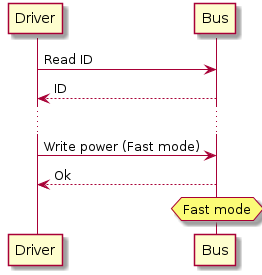
And that’s all there is to it.
Now, there are a few ways of working with this tool. You can run a local application which scans the current folder for compatible files and generates the diagrams. Run a local web-server via a docker image, which is what I prefer to do. Or use the online server, do keep in mind this option may cache your diagrams.
Likes and dislikes
I like that:
-
It’s text! Everyone can read it, both humans and machines (and thus, any application which handles plain text).
-
With a few simple commands, I can quickly write (yes, write) most of my diagrams. I feel that not having to switch between the mouse and keyboard made the whole process a lot faster.
-
Since the diagrams are text, I can handle it the same as code. And as such, I can easily integrate it into my development process. Want to see what has changed? Create a diff. Want to review changes? Use my review tool to highlight changes and report feedback.
-
It only does diagrams. Do one thing and do it well.
Dislikes:
- The image generator and I don’t always agree on the resulting placement of blocks and attempts to manipulate the placement generally do not help.
Proxy service
Recently I discovered a (for me) new feature, the proxy service. The same web server I already use for editing also has the option to receive text files and return the generated diagram via a plain URL.
I found this to be a powerful feature, as now I can place my text files inside a git repository and generate the corresponding images on the fly using this service.
Just like this:
Integration with my documentation workflow
I should note that my documentation is mainly on web pages, both professional and personal. Tools like MediaWiki, Markdown-based websites and Confluence are great to write and access documentation anytime and anywhere without the need for special software. Now the neat thing is, the proxy service integrates nicely into this workflow. I write my UML text, commit it to a repository, and generate a link to include the diagram in the documentation.
But how do I ensure the images match the text? Not only that, how to handle different versions of the same diagram? I still have to gain experience and find the best practice. My current idea is as follows:
- Have a separate git repository for each document/topic.
- Use branches; the trunk is for development and branches for specific versions.
- Documents only include images generated from branches.
Mixing source code and UML text
This depends on the project and how the code is organized. Within the workplace, I separate the UML and source code, as this is our convention.
Personally, I imagine combining certain design diagrams within the codebase combined within architecture records.